| |
|
|
|
|
|
|
|
|
|
| SYSTEM DESIGN ISSUES |
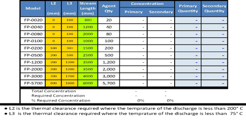
| • FirePro is a flooding agent – the layout of the risk is relevant to the design. |
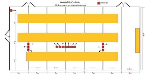 |
| ▪ Review any openings or ventilation in the Risk and assess the impact on Fire System. |
| ▪ The configuration of objects with special attention to the items which could initiate a fire. |
| ▪ The use of the Risk – normally manned ? |
| ▪ Clearances which need to be observed for safe egress from the Risk. |
| ▪ Separate earthing of all devices is required in High Voltage environments. |
| ▪ Clearances from objects for the FirePro units |
| ▪ Methods for detection of a fire and activation of the Aerosol Generators. |
| ▪ When selecting the particular FirePro units ensure even distribution of Gas – Stream Length? |
| ▪ Bracket selection and consider the use of Heavy Duty Brackets. |
| ▪ Wall or roof strengths compared to the weight of the FirePro units. |
| ▪ Use of Dust Covers on FirePro Units for protection from pest and debris. |
| ▪ Signage Requirements – compliance issues and the system will be in place for many years. |
| ▪ Self Activation temperature of 300°C; NO welding grinding near units – once installed. |
| SYSTEM DESIGN – RF INTERFERENCE ISSUES |
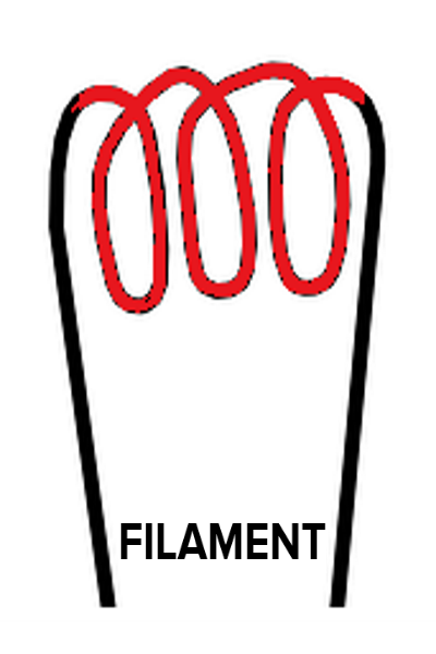 |
The FirePro electrical activation device is a small filament located within each aerosol generator.
The activator can be monitored by the system – this is done with a small amount of current through the activator circuit, and measured by the panel to ensure that the circuit is complete. A fault indicator at the panel will advise if the circuit becomes incomplete for any reason. The current required to activate the aerosol generators is small.
The presence of RF interference in the environment is very common and comes from many devices for example mobile phones, GPS devices, power inverters and many other sources. This interference needs to be eliminated from any control system as it can cause malfunction. The control panels and installation procedures that we use are all designed to eliminate any RF interference.
To eliminate the RF interference, SHIELDED FIRE RATED CABLE is required to be used on all Control systems. In addition installations must comply with wiring rules AS3000 section 3.9.8.3 segregation of different voltage levels. |
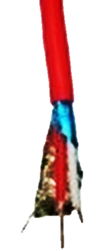
Fire-Rated
Shielded Cable |
| SYSTEM COMPLIANCE ISSUES |
| The decision about compliance is a process which needs to be clearly identified. This will be essentially at the direction of the client but will require your input as some risk areas could fall under multiple standards. Knowledge of the standards and regulations is necessary to guide the client through this process. |
| AS 4487 General & Land Based |
|
AS 5062 Mobile Plant & Equipment |
|
Local Protection |
|
Marine |
▪ Sigma Panel must be used.
▪ Shutdowns prior to discharge.
▪ Signage requirements.
▪ Remote activation requirements. |
▪ Risk analysis for system design.
▪ Compliant panel must be used.
▪ Shutdowns required.
▪ Signage. |
▪ Design to be agreed with client.
▪ Activation method.
▪ Shutdowns.
▪ Signage. |
▪ Understand Survey requirements.
▪ Correct FirePro Design Calculation.
▪ Installer certification required ?
▪ Compliant Panel to survey. |
   |
 |
|
   |
| METHODS OF ACTIVATION |
| ELECTRICAL |
| Electrical using Integrated Control Panel – Need to ensure that panel will be selected to comply with the relevant standard, and is capable of handling detection methods as well as the number of Aerosol units in the system. |
|
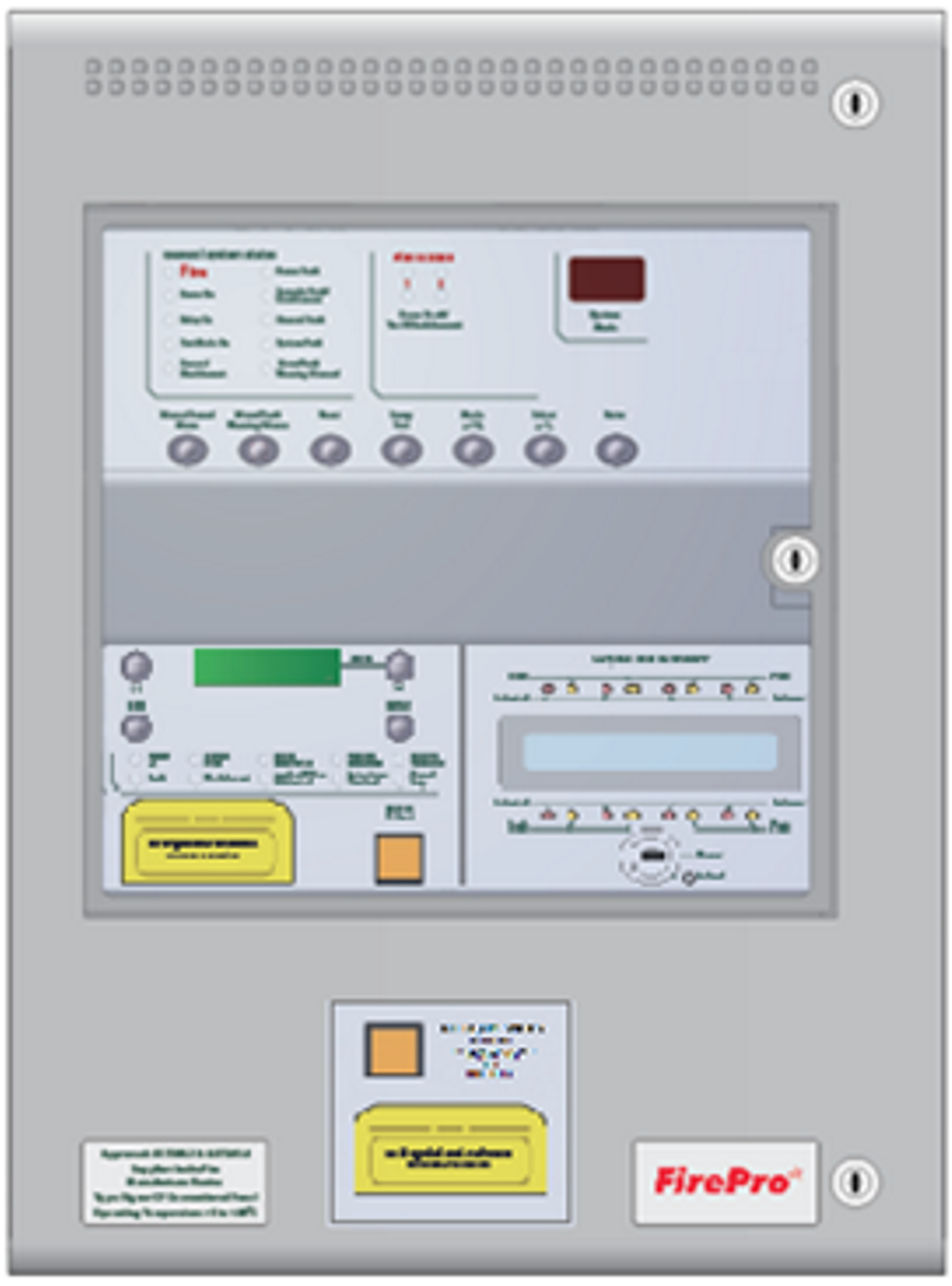
Standard AS Approved Fire Panel – signage and alarms are required. |
|
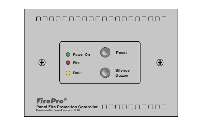
FPC-2 – 24vDC panel has monitored circuits for FirePro units and detection. Automatic & manual activation. Fire & fault output relays. |
|
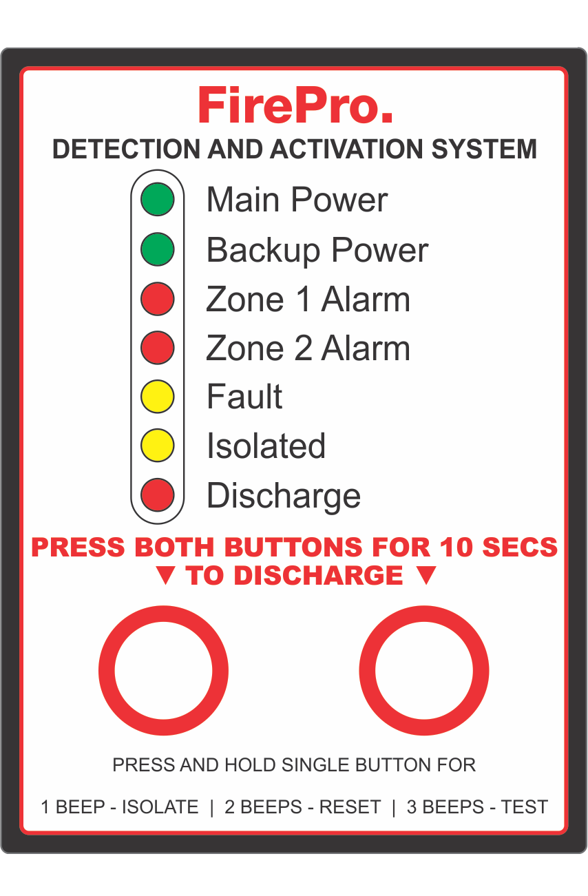
System Panel – has monitored circuits for FirePro units and detection, manual activation switch. Vehicle and Marine Versions available. |
|
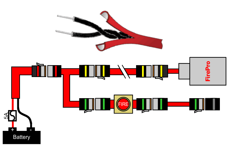
FP-08917 LHD Activator Autonomous fire suppression system • Single input detection loop • Linear heat detector cable • Compatible with FP-14053 Manual Switch |
| ELECTRICAL CONNECTIONS |
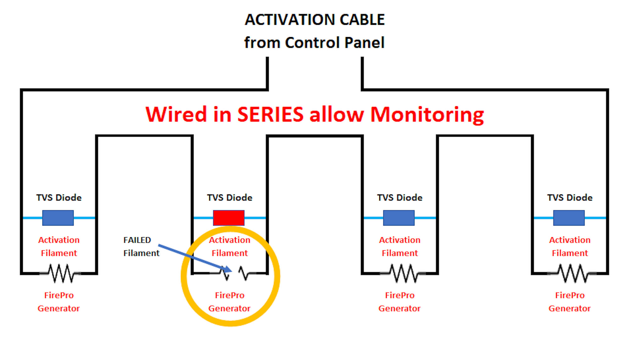 |
The FirePro Units are wired in SERIES to allow monitoring of the circuit. |
| On activation the circuit uses the filament to promote the electrical current to the next FirePro unit in the circuit. During activation the filament can break, and should this occur, the circuit would be broken and any FirePro units downstream from the break would not activate. |
To solve this issue – TVS Diodes are installed in each FirePro Unit.
These devices will activate if the filament fails – and on activation they will ensure that the circuit stays intact, and current is passed onto any downstream FirePro Units. Specification for TVS Diode – Voltage – 6v |
|
FirePro Limitations per Activation Circuit |
| Supply Voltage 24v – Max 4 FirePro Units |
Supply Voltage 12v – Max 2 FirePro Units |
| SYSTEM TESTING POINT |
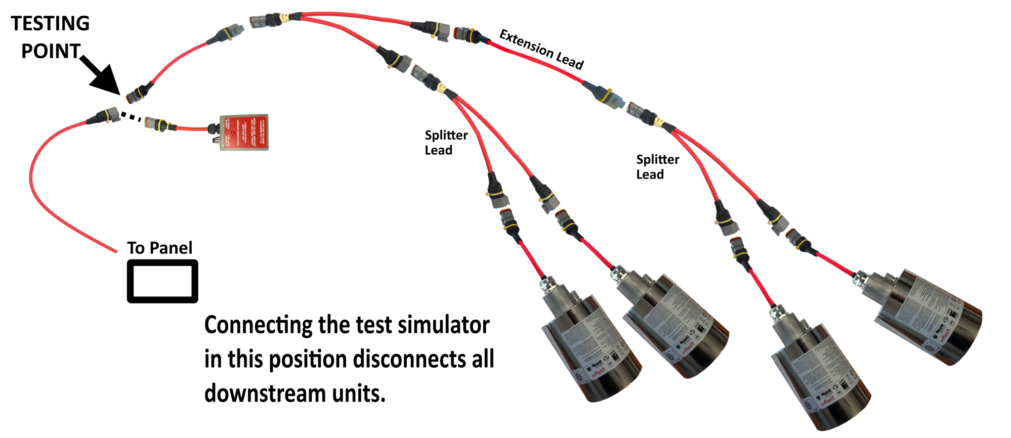 |
Due to regular testing requirements it may be good to install a System Testing point.
This is simply a break in the activation cable from the control panel. Attach Deutsch plugs which allow the FirePro Simulator to be connected. Locate where it is easy to access, and be signed as “FirePro System Test Point” |
| Suitable for: |
FP-08450 Marine Control Panel
FP-08451 Mobile Plant Control Panel
FP-08100 Control Panel
FP-08917 Local Application System |
| BULB THERMAL ACTIVATOR – B T A |
Suitable for local protection systems only – not part of any AS Systems.
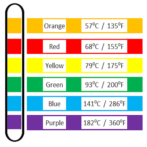
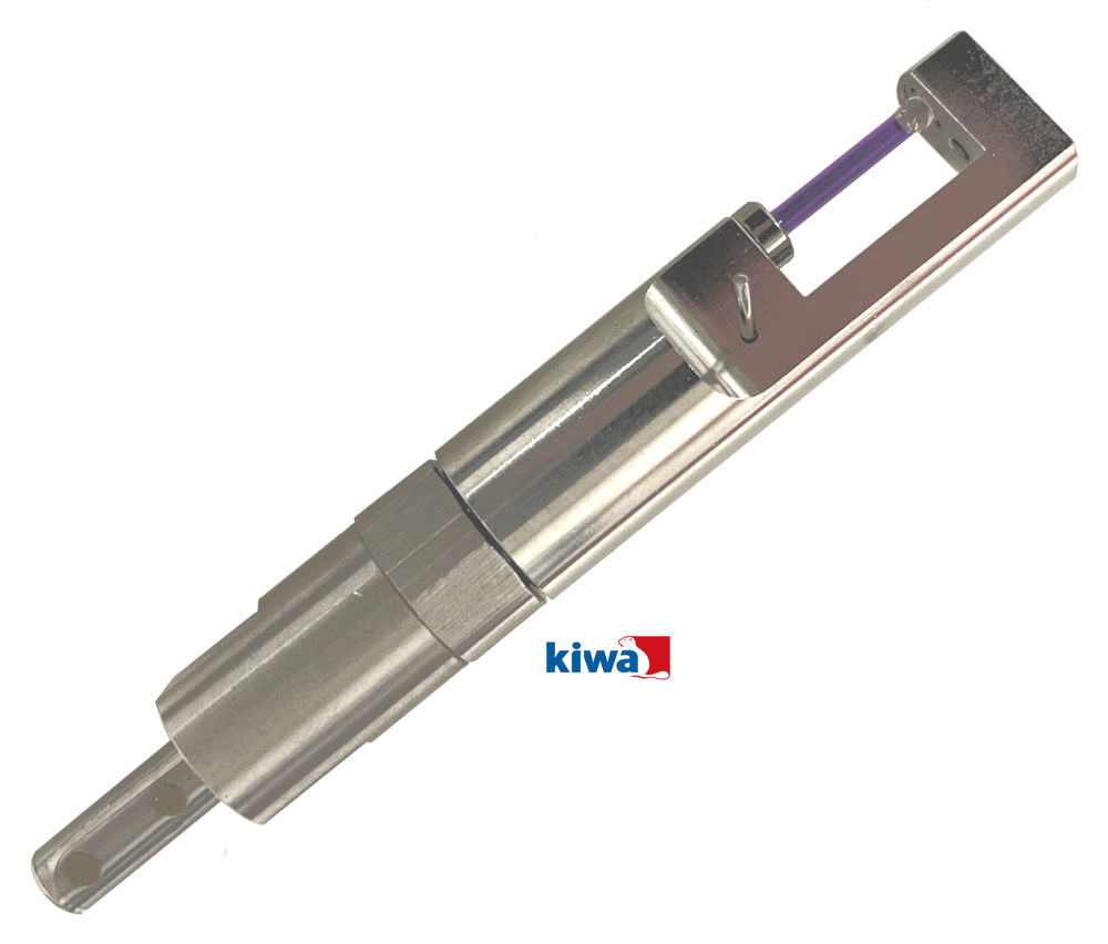
Self-contained, automatic and temperature controlled activation system. The FirePro BTA V3 performs the functions of fire detection and automatic activation of the fire extinguishing aerosol generator with the use of a bulb thermal sensor at a pre- selected temperature. At the predetermined operating temperature the glass bulb ‘bursts’, causing the thermal mechanism to actuate the built-in firing pin, and ignites the solid compound of the Thermal Actuator.
The Thermo Bulb is a fast response unit featuring improved strength and sensitivity characteristics. Response Time Index RTI 24m/s. The mechanism that remains in a static has a product life of 15 years. |
|  |
  |