| INSTALLATIONS – VEHICLE & MOBILE PLANT |
| |
|
|
|
|
|
|
|
| Applications |
| Ideal for vehicles and mobile plant in the mining, logistics, construction and forestry industries, suitable for to all sizes of vehicle and mobile plant. No pipework, and space and weight saving. |
 |
Compliance &
Design Issues |
The system will be designed to AS 5062. The basis of the calculation will be on GROSS VOLUME of the risk. LEAKAGE AREA will be identified on the design calculation. There are 3 types of design calculations available – selection will depend on the risk AS 5062 – allows additional leakage from Risk ▪ General – limited leakage from Area ▪ Lithium – specific for this Risk type. Risk Assement required to complay with AS 5062. |
| Components & System Schematic |
FP-08451 – Control Panel
FP-08945 – Panel Cover
FP-08872 – Battery Backup
FP-08860 – Shutdown Module
FP-08850 – Delay Discharge
FP-08879 – Voltage Relay
FP-08825 – Thermal Fuse
FP-14053 – Manual Actuator
FP-14016 – Battery Lead
|
|
|
|
| Areas to Focus |
| Positioning of FirePro Units |
Cable |
Deutsch Plug Connections |
Accidental Discharge |
Test Equipment |
Faults |
|
|
|
|
 |
|
Damage to wiring or water ingress to connections may be a fault.
▪ The Fault LED will light.
▪ The panel will beep in codes:
– 1 beep On Circuit 1 Alarm
– 2 beeps On Circuit 2 Alarm
– 3 beeps On Discharge Circuit
– 4 beeps On Siren Circuit – V4 Panel
▪ Most faults are power supply
▪ Panel is 9-30vDC – fail below 7.5v
▪ Battery Charge 25v – LED Charging
▪ Batt takes over when below 25vDC
▪ Voltage Relay below 25.6v
– incoming power cut off.
– Backup will power system.
– Engages supply above 26.8vDC. |
Consider the installation of a

|
Allow for maintenance.
▪ Locate clear of mechanical-weather.
▪ Use of HD brackets.
▪ Minimum safe clearances.
▪ Means of egress or rescue. |
Cable install is critical.
▪ Consider Cable path.
▪ Use conduit where exposed.
▪ Cable to be secured with P-Clips. |
Deutsch Plug Connections
▪ Follow pin wiring Diagram.
▪ Female plugs – down facing.
▪ Ensure heatshrink COOLS. |
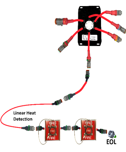
DETECTION CIRCUIT 1
▪ only way the system can activate.
▪ Water ingress short -> activation.
▪ Female Plugs installed down facing.
▪ Cover connection with HeatShrink. |
▪ Test Module connected first.
▪ Plug directly to panel.
▪ This isolates all downstream units.
▪ Runs on 9v Battery. |
  |